As a conclusion to my computer organization course, our final project was to implement a five stage pipeline constructed in Verilog over an FPGA partially implementing the MIPS instruction set.
Abstract
The following details the development of a five stage pipeline constructed on Xilinx’s Vivado in Verilog over an FPGA partially implementing the MIPS instruction set. In its current configuration, it supports only basic R-Format instructions like add, sub, and, or, etc. as well as basic I-Format instructions like lw and sw. Additionally, in this final revision of the pipeline, data forwarding to the instruction decode stage was implemented along with write-back of the register file on the negative edge of the clock both in order to reduce the penalty for data hazards. It achieves this functionality by making use of five pipeline registers, a control unit, an ALU, a number of multiplexors, dedicated memories for instructions and data, and a register file.
Introduction
This simple MIPS pipeline implementation begins with the first pipeline register, the instruction memory, and a 32-bit adder that all make up the instruction fetch stage. In this simple implementation, the program counter register (the first pipeline register) has only a single input, which is its current value + 4. If the design were extended to support branch and jump instructions, this input would be equipped instead with a multiplexer to control where in the program execution jumped to next. The current PC value is used to select the corresponding instruction from the instruction memory, and this instruction is set up on the input of the IF/ID pipeline register.
The next stage that the instruction enters once it has been written to the IF/ID register is the instruction decode stage. In this implementation, this stage is where, using the encoded instruction, the instruction’s control signals are initially generated by the control unit, where the immediate field of the instruction is sign-extended, where the destination register is selected for later use, and where the instruction operands are selected and read from the register file. Data is also written back to the register file in this stage on the negative edge of the clock if a “wreg” signal is asserted by the instruction in the write-back stage (more on this later). This stage also includes the logic that enables forwarding to this stage, which will be discussed in more detail later.
Once the instruction has effectively been interpreted in the ID stage, and once its control signals and operands are written to the next pipeline register, the ID/EXE register, the instruction is in the execution stage. It is in this stage where the ALU produces the result of R-Format instructions and the memory addresses for lw and sw instructions. Depending on the type on instruction, the second ALU operand will be selected to produce the desired result. If a lw or sw, the immediate containing the offset is selected, whereas the second operand read from the register file (“qb”) will be selected for an R-Format instruction. Note that “qb” is passed to the next stage as well in case of a sw instruction, as it will be the data to be stored.
When the ALU result and other signals have been written to the fourth pipeline register, the EXE/MEM register, the instruction is in the memory stage. In this stage, data can be read from memory at the target address calculated by the ALU in the previous stage, or data (“qb”) can written to the data memory at that target address if a “wmem” signal is asserted, indicating that the instruction in this stage is to write to memory (i.e., a sw). R-Format instructions, on the other hand, simply pass through this stage, with the ALU result making its way to next pipeline stage.
An instruction is in the fifth and final stage of this pipeline once it has been written to the MEM/WB pipeline register. This stage is simply comprised of the MEM/WB register, a multiplexor to select the data source for the instruction’s write, and essentially shares the register file with the instruction decode stage. This “sharing” does not lead to a physical hazard, however, because instructions in both stages interact with different ports.
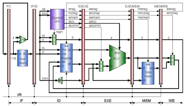
The result is a functioning five stage pipeline that looks something like this:
However, some improvements can be made. Consider the following instruction sequence:
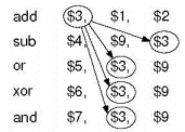
Without any changes, the more primitive design would incur a significant stall penalty due to the lack of availability of the result to be stored in register $3. Thus, the final portion of this project was dedicated to implementing a means of data-forwarding. Before discussing the approach to forwarding employed, a simple change was also introduced in the register file that allows it to write data on the negative edge of the clock. While this improvement does not solve all of the data hazards, it does mitigate some and also reduces the need for forwarding in many cases. Because an instruction currently in the write-back stage can write its data on the negative edge of the clock signal, this means that an instruction currently in the decode stage that depends on the result of that instruction in the write-back stage can obtain the correct data from that common register without requiring any forwarding, as it reads asynchronously for the duration of the clock cycle. For introducing forwarding, while different approaches exist and each offer unique advantages, the approach employed in this project was to implement forwarding to the instruction decode stage from both the execution stage and memory stage.
In this approach, data hazards between instructions can all be resolved within the decode stage. This means that no additional forwarding is needed to the execution stage, as if there was a data hazard when the instruction was being decoded, it would have been forwarded the correct data at that point. Of course, a stall is still needed in the instance of a load-use data hazard, but for the hazards between R-Format instructions, this method is ideal. An additional advantage that this method has is that it inherently also supports forwarding needed for branch data-hazards. It is common to relocate the evaluation of branch conditions to the ID stage, and therefore sometimes forwarding is needed to obtain the correct operands. In this way, because the forwarding hardware is already implemented in the ID stage for other types of instructions, additional (forwarding) hardware is not needed for branch instructions. To implement forwarding in this manner, two 32-bit 4 to 1 multiplexers needed to placed before the ID/EXE pipeline register. These multiplexers would be responsible selecting the appropriate source for the needed operand each using their own 2-bit select signal generated by the control unit. In this way, the control unit (which the forwarding unit has effectively been built into) determines if a data-hazard is present, and if so, generates the necessary selection signals to get the necessary data to the right spot in the decode stage.
To detect when a data hazard occurs, the control unit had to be outfitted with a few additional inputs: ewreg, ern, mwreg, mm2reg, and mrn (note that em2reg is also added, but is only used to detect if the instruction in the execution stage is a lw instruction, which can be used for identifying load-use data hazards in slightly more sophisticated implementations). Then, the logic used to identify data hazards within the control unit was as follows:
- If the rs register number of the instruction in the ID stage matches the destination register number (ern) of the instruction in the EXE stage, AND the instruction in the EXE stage will eventually write back to the register file (indicated by ewreg being HIGH), then the data read from the register file is out of date, so select the data from the output of the ALU to be written to ID/EXE as the operand.
- If the rs register number of the instruction in the ID stage matches the destination register number (mrn) of the instruction in the MEM stage, AND the instruction in the MEM stage will eventually write back to the register file (indicated by mwreg being HIGH), then:
- If mm2reg low, this indicates that the ALU result will eventually be written back to the register file, and therefore the ALU result from the MEM stage should be forwarded to the ID stage, so select it to be written to ID/EXE as the rs operand.
- If mm2reg is HIGH, this indicates that the data output of the data memory will eventually be selected to be written back to the register file, and therefore the data output (do) should be forwarded to the ID stage, so select it to be written to ID/EXE as the rs operand. Likewise, the same logic is implemented but making the comparisons with the “rt” register number.
To actually solve the data hazards, the control unit has two additional outputs. Each is the 2-bit selection signal used to choose one of the four potential sources for each forwarding multiplexer. In this way, data hazards can effectively be detected and solved. Also, note that when one of the operand’s register numbers matches that of multiple earlier instructions that occurred immediately before it, such that they are still in the EXE and MEM stage, it implicitly works out that the most recent instruction with that destination will have its data forwarded. This is detailed in the source code.
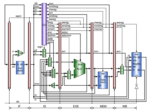
Once the forwarding hardware is introduced, the resulting pipeline looks something like this: